Heat transfer plays a critical role in almost every industrial process. Whether it is cooling hot gases, recovering waste heat, or maintaining process temperatures, industries rely on efficient heat exchangers to optimize performance and reduce energy consumption. Among the many types of heat exchangers available, the Fin Tube Heat Exchanger stands out for its ability to maximize heat transfer in applications involving air or gas.
In this guide, we’ll explore what a fin tube heat exchanger is, how it works, its construction materials, different fin tube designs, advantages, limitations, and the industries where it is commonly used.
What Is a Fin Tube Heat Exchanger?
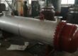
A Fin Tube Heat Exchanger is a type of heat exchanger that uses extended surfaces, known as fins, attached to tubes to increase the available heat transfer area. The fins significantly improve heat exchange efficiency, particularly when one of the fluids involved is air or gas, which typically has a lower heat transfer coefficient than liquids.
By increasing the surface area without greatly increasing the size of the equipment, fin tube heat exchangers can transfer more heat while maintaining a compact design.
Simply put, fins help the heat exchanger do more work without requiring larger tubes or additional equipment.
How Does a Fin Tube Heat Exchanger Work?
The working principle is straightforward.
One fluid flows through the tubes while another fluid, usually air or gas, flows around the finned exterior surface. Heat transfers from the hotter fluid to the cooler fluid through the tube wall and fins.
The fins increase the external surface area exposed to the surrounding fluid, allowing more heat to be transferred in a shorter amount of time.
For example:
- Hot water flows inside the tubes.
- Ambient air passes over the finned surface.
- Heat moves from the water through the tube wall and fins into the air.
- The air temperature rises while the water cools down.
This enhanced surface area makes fin tube heat exchangers highly effective in air heating and cooling applications.
Main Components of a Fin Tube Heat Exchanger
A typical fin tube heat exchanger consists of:
Tubes
The tubes carry the process fluid and act as the primary pathway for heat transfer.
Fins
Thin metal extensions attached to the outside of the tubes increase the heat transfer surface area.
Tube Sheets
These secure the tubes in place and separate the fluid streams.
Casing or Frame
Provides structural support and directs airflow across the finned tubes.
Headers
Distribute fluid evenly throughout the tube bundle.
Materials Used in Fin Tube Heat Exchangers
Material selection depends on operating temperature, pressure, corrosion resistance requirements, and budget.
Carbon Steel
- Economical option
- Good mechanical strength
- Suitable for general industrial applications
Stainless Steel
- Excellent corrosion resistance
- Suitable for chemical and food processing industries
- Long service life
Copper
- Outstanding thermal conductivity
- Commonly used in HVAC and refrigeration systems
Aluminum
- Lightweight
- High thermal efficiency
- Frequently used for fins
Copper-Nickel Alloys
- Excellent seawater resistance
- Common in marine and offshore applications
Titanium
- Superior corrosion resistance
- Used in highly aggressive environments
Types of Finned Tubes
The performance of a fin tube heat exchanger largely depends on the fin design. Several fin configurations are available to suit different operating conditions.
Extruded Fin Tubes
Extruded fin tubes are manufactured by mechanically forming fins from an outer aluminum sleeve around the base tube.
Advantages:
- Excellent mechanical strength
- Strong fin-to-tube bond
- Suitable for outdoor environments
L-Foot Fin Tubes
The fin strip is wrapped around the tube and secured using an L-shaped foot.
Advantages:
- Cost-effective
- Good heat transfer performance
- Suitable for moderate temperatures
Embedded (G-Fin) Tubes
The fin strip is embedded into a machined groove on the tube surface.
Advantages:
- Strong mechanical attachment
- Reliable thermal performance
- Suitable for higher temperatures
Welded Fin Tubes
The fins are welded directly onto the tube surface.
Advantages:
- Excellent durability
- Suitable for high-pressure and high-temperature applications
- Preferred in power plants and petrochemical facilities
Spiral Fin Tubes
Fins are helically wound around the tube to maximize surface area.
Advantages:
- Uniform heat distribution
- Efficient airflow characteristics
- Common in industrial heaters and coolers
Common Examples of Fin Tube Heat Exchangers
Fin tube heat exchangers are used in many everyday and industrial systems.
Examples include:
- Air coolers
- Radiators
- HVAC heating coils
- Air conditioning condensers
- Refrigeration evaporators
- Boiler economizers
- Waste heat recovery units
- Dry cooling systems
- Industrial air heaters
- Generator cooling systems
Design Factors for Fin Tube Heat Exchangers
Proper design is essential for achieving optimal performance and efficiency.
Heat Transfer Requirements
The required heating or cooling duty determines the exchanger size and surface area.
Fin Geometry
Factors include:
- Fin height
- Fin spacing
- Fin thickness
- Fin density
These directly affect heat transfer rates and pressure drop.
Airflow Characteristics
The velocity and direction of airflow significantly impact performance.
Fluid Properties
Properties such as viscosity, thermal conductivity, density, and specific heat influence heat transfer calculations.
Operating Temperature
Higher temperatures require materials capable of maintaining structural integrity under thermal stress.
Corrosion Environment
Material selection must account for exposure to moisture, chemicals, or corrosive gases.
Pressure Drop Limits
The design should balance heat transfer performance with acceptable pressure losses.
Maintenance Accessibility
Easy access for cleaning and inspection helps extend equipment life and maintain efficiency.
Advantages of Fin Tube Heat Exchangers
Fin tube heat exchangers offer several important benefits.
Higher Heat Transfer Efficiency
The additional surface area significantly improves thermal performance.
Compact Design
More heat transfer can be achieved without increasing equipment size.
Energy Savings
Improved efficiency reduces energy consumption and operating costs.
Lower Equipment Footprint
Useful where installation space is limited.
Flexible Design Options
Available in various materials, fin types, and configurations.
Suitable for Gas-to-Liquid Applications
Particularly effective when air or gas is one of the heat transfer media.
Limitations of Fin Tube Heat Exchangers
Like any equipment, fin tube heat exchangers have certain drawbacks.
Fouling Risk
Dust, dirt, and debris can accumulate between fins and reduce performance.
More Complex Cleaning
Closely spaced fins may require specialized cleaning methods.
Higher Initial Cost
Advanced fin designs and premium materials can increase upfront investment.
Potential Mechanical Damage
Thin fins may be vulnerable to impact during handling or maintenance.
Industrial Applications of Fin Tube Heat Exchangers
Fin tube heat exchangers are widely used across multiple industries.
HVAC Industry
Used in heating coils, cooling coils, condensers, and evaporators.
Power Generation
Applied in air-cooled condensers, boiler economizers, and waste heat recovery systems.
Petrochemical Industry
Used for cooling process streams and recovering heat from exhaust gases.
Oil and Gas Industry
Supports gas processing, compressor cooling, and offshore operations.
Food and Beverage Industry
Used in refrigeration systems and temperature-controlled production processes.
Chemical Processing
Provides efficient heating and cooling for various chemical reactions.
Marine Industry
Used in engine cooling and seawater-resistant heat exchange systems.
Manufacturing Plants
Supports compressed air cooling, furnace cooling, and process temperature control.
Maintenance Best Practices
Regular maintenance ensures reliable operation and maximum thermal efficiency.
Routine Cleaning
Remove dust, dirt, and deposits from fin surfaces to maintain airflow.
Inspect for Corrosion
Regularly check tubes, fins, and joints for signs of corrosion.
Monitor Pressure Drop
Unexpected increases may indicate fouling or blockage.
Check for Leaks
Inspect headers, tube connections, and welded joints.
Straighten Damaged Fins
Bent fins can restrict airflow and reduce performance.
Schedule Performance Audits
Periodic thermal performance evaluations help identify efficiency losses before they become major problems.
Fin Tube Heat Exchanger vs Plain Tube Heat Exchanger
| Feature | Fin Tube Heat Exchanger | Plain Tube Heat Exchanger |
| Surface Area | High | Lower |
| Heat Transfer Rate | Higher | Lower |
| Equipment Size | More Compact | Larger |
| Air Cooling Efficiency | Excellent | Moderate |
| Initial Cost | Higher | Lower |
| Energy Efficiency | Better | Lower |
Future Trends in Fin Tube Heat Exchanger Technology
Modern industries continue to demand greater energy efficiency and sustainability. As a result, manufacturers are focusing on:
- Advanced fin geometries
- High-performance alloys
- Improved corrosion-resistant coatings
- Enhanced computational design methods
- Waste heat recovery optimization
- Compact and lightweight exchanger designs
These developments are helping industries reduce energy consumption while improving process performance.
Conclusion
Fin tube heat exchangers are among the most efficient solutions for transferring heat between fluids when air or gas is involved. By increasing the available heat transfer surface area through the use of fins, these exchangers deliver higher thermal efficiency, reduced energy consumption, and compact system designs.
From HVAC systems and power plants to chemical processing facilities and food manufacturing operations, fin tube heat exchangers have become an essential component of modern thermal management systems. With proper design, material selection, and maintenance, they provide reliable and cost-effective performance for a wide range of industrial applications.